






Build an Arduino Smart Solar Tracking System for Science Fair
📊 Project Overview
- Difficulty: Intermediate
- Time Required: 4–5 hours
- Age Group: 13–24 years
- Subject: Renewable Energy, Electronics, Coding
- Total Cost: ₹800–₹1200
📋 Table of Contents
☀️ Introduction to Solar Tracking
Did you know that standard solar panels lose a massive amount of potential energy because the sun moves across the sky while the panels stay completely still? Building an arduino smart solar tracking system project is the perfect way to solve this real-world problem. By making the solar panel follow the sun, we can increase energy collection by up to 30%!
In this comprehensive tutorial, we will build an automated system that senses light direction and rotates the solar panel to face the brightest light source. This is one of the most popular and impressive science projects for school exhibitions (CBSE, ICSE, and state boards) and college engineering fairs.
Whether you are 13 years old or an engineering student, this project will teach you the fundamentals of green energy, sensor integration, and motor control. Let’s dive in and harness the power of the sun!
🧠 What You Will Learn
Before we jump into the build, let’s look at the core concepts you will master by completing this project. This isn’t just about putting wires together; it’s about understanding the engineering behind modern renewable technology.
💡 Sensor Logic
- Understanding Light Dependent Resistors (LDR)
- Reading analog values with Arduino
- Creating voltage dividers
⚙️ Motor Control
- Working with Servo Motors (MG90/MG996R)
- Generating PWM signals
- Mapping sensor data to angles
🔋 Power Management
- Wiring Li-Ion batteries safely
- Using charging modules
- Isolating motor power from logic power
📦 Components Needed
To build our arduino smart solar tracking system project, we need a mix of mechanical parts, electronic sensors, and a microcontroller. You can easily buy components from our shop if you don’t have them lying around.
🖥️ Arduino Uno
- The brain of our project
- Processes sensor data
- Controls the servo motor
📡 LDR Sensor Modules (x2)
- Detects light intensity
- Provides analog output
- Acts as our “eyes”
⚙️ Servo Motor (MG90 or MG996R)
- Rotates the solar panel
- Metal gears for durability
- 180-degree movement
🔋 Power Supply
- 2x 18650 Li-Ion Batteries
- Battery Holder
- On/Off Switch
Budget Breakdown
| Component | Quantity | Estimated Price (₹) |
|---|---|---|
| Arduino Uno R3 with Cable | 1 | ₹450 |
| LDR Sensor Module | 2 | ₹100 |
| MG90 / MG996R Servo Motor | 1 | ₹200 – ₹350 |
| Small Solar Panel (5V/9V) | 1 | ₹150 |
| Li-Ion Batteries + Holder + Switch | 1 set | ₹250 |
| Breadboard & Jumper Wires | 1 set | ₹100 |
| Total Estimated Cost | ₹1250 – ₹1400 |
✅ Pro Tip: Mechanical Build
You can use thick cardboard, MDF wood, or 3D printed parts for the stand. The key is making sure the solar panel is balanced on the servo motor so it doesn’t struggle to turn.
🔌 How It Works
The magic behind this project lies in a simple comparison. We place two LDR (Light Dependent Resistor) sensors on opposite sides of the solar panel. An LDR changes its electrical resistance based on how much light hits it. When it is bright, the resistance drops. When it is dark, the resistance goes up.
💡 The Logic Explained
The Arduino continuously reads the analog values from both LDRs. If the right LDR receives more light than the left LDR, the Arduino tells the servo motor to rotate to the right. It keeps rotating until both LDRs receive the exact same amount of light, meaning the panel is facing directly at the sun!
We use a small delay in our code to prevent the motor from jittering back and forth constantly. By adjusting the sensitivity in the code, we can make the tracking perfectly smooth. If you are a beginner, reading up on our Arduino basics for beginners guide can help you understand analog signals better.
🗺️ Circuit Diagram
Wiring the system is straightforward. The most important rule is to ensure all grounds (GND) are connected together on the breadboard.

Figure 1: Circuit diagram of the Smart Solar Tracking System. Ensure you connect the servo to a PWM pin (like Pin 9).
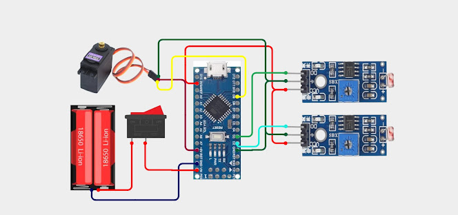
⭐ Key Insight: Never power a heavy metal-gear servo (like the MG996R) directly from the Arduino’s 5V pin. Always use an external power source (like the Li-Ion batteries) for the motor, and ensure the battery ground is connected to the Arduino ground.
🛠️ Step-by-Step Build
Let’s put everything together. Follow these steps carefully to ensure a smooth build process.
Prepare the Base and Stand
- Take a solid base (like a wooden plank or thick acrylic sheet) to mount your project.
- Fix an L-shaped bracket or a vertical pillar to hold the servo motor.
- Secure the servo motor firmly to the pillar using screws. It should not wobble.
Mount the Solar Panel and Sensors
- Attach a flat platform (cardboard or plastic) to the servo motor horn.
- Glue or tape your solar panel to this platform.
- Mount one LDR module on the far left edge of the solar panel, and the second LDR on the far right edge.
- Ensure both sensors are facing straight up, aligned with the panel.
Wiring the Electronics
- Connect the VCC pins of both LDR modules to the 5V line on your breadboard.
- Connect the GND pins of both LDR modules to the GND line on the breadboard.
- Connect the OUT/A0 pin of the Left LDR to Arduino Analog Pin A0.
- Connect the OUT/A0 pin of the Right LDR to Arduino Analog Pin A1.
- Connect the Servo Signal wire (usually yellow or orange) to Arduino Digital Pin 9.
Connecting Power
- Place the two 18650 Li-Ion batteries into the battery holder.
- Wire the positive wire through the switch, then to the Servo’s VCC (Red wire).
- Connect the battery negative wire to the breadboard GND line.
- Connect the Arduino GND to the same breadboard GND line.
- Power the Arduino either via USB or by connecting the battery positive to the Vin pin.
💻 The Arduino Code
Below is the complete code for our arduino smart solar tracking system project. It uses the standard Servo.h library, which comes pre-installed in the Arduino IDE. Copy and paste this into your editor, select your COM port, and hit upload.
Arduino C++
#include <Servo.h>

Servo trackerServo;  // Create servo object

// Define LDR sensor pins
const int ldrLeftPin = A0;

const int ldrRightPin = A1;

// Variables to store sensor readings
int ldrLeftValue = 0;
int ldrRightValue = 0;

// Initial servo angle (starting at center)
int servoAngle = 90;

// Sensitivity threshold to prevent jitter
const int threshold = 20;

void setup() {
Serial.begin(9600);           // Start serial monitor for debugging
trackerServo.attach(9);       // Attach servo to digital pin 9
trackerServo.write(servoAngle); // Set initial position to 90 degrees
delay(1000);                  // Wait for servo to reach position
}

void loop() {
// Read analog values from LDRs (0 to 1023)
ldrLeftValue = analogRead(ldrLeftPin);
ldrRightValue = analogRead(ldrRightPin);

// Print values for debugging
Serial.print("Left LDR: ");
Serial.print(ldrLeftValue);
Serial.print(" | Right LDR: ");
Serial.println(ldrRightValue);

// Calculate the difference between the two sensors
int difference = abs(ldrLeftValue - ldrRightValue);

// Only move if the difference is greater than the threshold
if (difference > threshold) {
if (ldrLeftValue > ldrRightValue) {
// Left side is brighter, move left
if (servoAngle < 180) {
servoAngle++;
trackerServo.write(servoAngle);
}
} else if (ldrRightValue > ldrLeftValue) {
// Right side is brighter, move right
if (servoAngle > 0) {
servoAngle--;
trackerServo.write(servoAngle);
}
}
}

// Small delay for smooth movement
delay(25);
}
✅ Pro Tip: Adjusting Sensitivity
If your servo vibrates constantly without moving, increase the threshold variable to 30 or 40. If it reacts too slowly, lower it to 10. You can also adjust the delay(25); at the bottom to control the speed of the motor.
🔧 Troubleshooting Guide
Building hardware sometimes comes with hiccups. If your system isn’t working on the first try, don’t panic! Check these common issues.
❌ Problem: The servo motor keeps resetting or twitching violently.
- Solution 1: You are likely drawing too much current from the Arduino. Ensure the servo is powered by an external battery, not the Arduino’s 5V pin.
- Solution 2: Check if your batteries are fully charged.
- Solution 3: Ensure the grounds (GND) of the battery, Arduino, and Servo are all connected together.
❌ Problem: The panel tracks away from the light instead of towards it.
- Solution: The logic is reversed. Simply swap the jumper wires going into A0 and A1 on the Arduino, OR change the
>signs to<in the if-statements in the code.
❌ Problem: The system is not reacting to light at all.
- Solution 1: Check the Serial Monitor in the Arduino IDE. Are the LDR values changing when you shine a flashlight on them? If not, check your LDR wiring.
- Solution 2: Some LDR modules have a tiny potentiometer (screw) on them. Use a screwdriver to adjust their sensitivity until they give good readings.
💬 Frequently Asked Questions
❓ Can I power the Arduino using the solar panel itself?
Yes! You can connect the output of the solar panel to a TP4056 charging module, which charges a Li-Ion battery. The battery then powers the Arduino and motor. This makes it a truly 100% self-sustaining project.
❓ What is the difference between MG90 and MG996R servos?
The MG90 is a small micro-servo with metal gears, suitable for very light, small solar panels. The MG996R is a much larger, high-torque servo motor that can handle heavier loads, like thick acrylic panels or larger solar cells.
❓ Can I make this a dual-axis tracker?
Absolutely! A dual-axis tracker moves up/down as well as left/right. You would need 4 LDR sensors (top, bottom, left, right) and 2 servo motors to achieve this. It’s a great upgrade for an advanced science fair project.
🛒 Ready to Build Your Solar Tracker?
We stock high-quality Arduino Unos, genuine metal-gear servos, and precision LDR sensors at student-friendly prices. Get everything delivered fast across India!