





Smart Traffic Light System Using Arduino: Complete DIY Guide
- Are you looking to build an intelligent traffic control system using Arduino? This comprehensive guide will walk you through creating a smart traffic light system that mimics real-world traffic management. Perfect for students, hobbyists, and robotics enthusiasts!
📋 Table of Contents
🚦 What is a Smart Traffic Light System?
A smart traffic light system is an automated traffic control project that uses Arduino microcontroller to manage traffic flow at intersections. Unlike traditional timer-based systems, smart systems can adapt to traffic density using sensors, making them more efficient and realistic.
🎯 Key Features
- Automated signal control
- Programmable timing sequences
- Four-way intersection management
- Real-time traffic light switching
- Emergency vehicle priority
⚡ Smart Capabilities
- Sensor-based density detection
- Dynamic timing adjustment
- IoT integration ready
- Customizable logic
- Scalable design
💡 Why Build This Arduino Project?
🎓 Educational Value
- Microcontroller Programming: Learn C/C++ in a practical context
- Real-World IoT: Understand how smart city systems work
- Traffic Management: Grasp engineering concepts behind traffic control
- Hands-On Electronics: Build practical circuits and debug hardware
🏆 Practical Applications
- Perfect for school science fair projects
- Excellent for college engineering demonstrations
- Great portfolio piece for aspiring engineers
- Ideal for robotics competition entries
🔧 Components Required for Smart Traffic Light System
Essential Components
Arduino Board
- Arduino UNO (recommended)
- Arduino Mega (advanced)
LEDs
- 12x Red LEDs (5mm)
- 12x Yellow LEDs (5mm)
- 12x Green LEDs (5mm)
Other Components
- 12x 220Ω resistors
- Breadboard
- Jumper wires
- USB cable
💰 Cost Estimate
Basic Setup: $28-46 USD
Advanced Setup (with sensors): $48-70 USD
Perfect for students on a budget! All components readily available online.
📐 Circuit Diagram and Connections
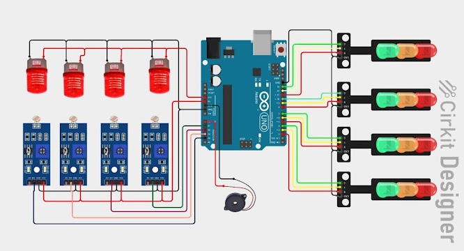
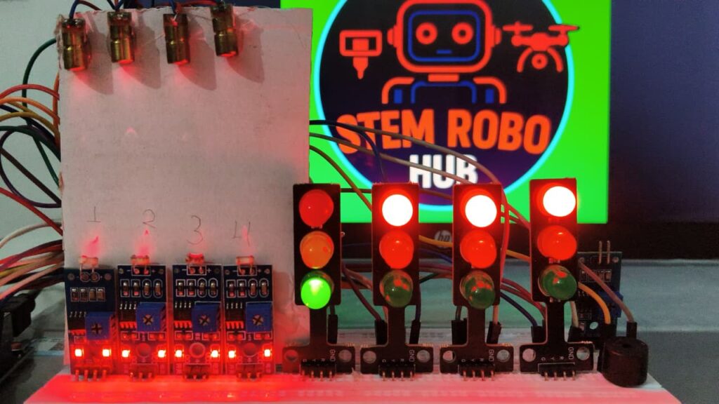
All components required for building the smart traffic system
Pin Configuration
🔴 Road 1 (North)
- Red LED → Pin 2
- Yellow LED → Pin 3
- Green LED → Pin 4
🔴 Road 2 (East)
- Red LED → Pin 5
- Yellow LED → Pin 6
- Green LED → Pin 7
🔴 Road 3 (South)
- Red LED → Pin 8
- Yellow LED → Pin 9
- Green LED → Pin 10
🔴 Road 4 (West)
- Red LED → Pin 11
- Yellow LED → Pin 12
- Green LED → Pin 13
Complete circuit diagram showing all LED connections to Arduino UNO
⚠️ Important: Always connect a 220Ω resistor in series with each LED to prevent burnout. The longer leg of the LED is positive (anode) and shorter leg is negative (cathode).
💻 Arduino Code for Smart Traffic Light System
Basic Traffic Light Code
C++
// Arduino Smart Traffic Light System
// Define LED pins for each direction

// Road 1 - North
int red1 = 2;
int yellow1 = 3;
int green1 = 4;

// Road 2 - East
int red2 = 5;
int yellow2 = 6;
int green2 = 7;

// Road 3 - South
int red3 = 8;
int yellow3 = 9;
int green3 = 10;

// Road 4 - West
int red4 = 11;
int yellow4 = 12;
int green4 = 13;

// Timing variables (in milliseconds)
int greenDelay = 5000;   // 5 seconds
int yellowDelay = 2000;  // 2 seconds

void setup() {
  // Initialize all LED pins as OUTPUT
  pinMode(red1, OUTPUT);
  pinMode(yellow1, OUTPUT);
  pinMode(green1, OUTPUT);

  pinMode(red2, OUTPUT);
  pinMode(yellow2, OUTPUT);
  pinMode(green2, OUTPUT);

  pinMode(red3, OUTPUT);
  pinMode(yellow3, OUTPUT);
  pinMode(green3, OUTPUT);

  pinMode(red4, OUTPUT);
  pinMode(yellow4, OUTPUT);
  pinMode(green4, OUTPUT);

  // Start with all red lights on (safe state)
  digitalWrite(red1, HIGH);
  digitalWrite(red2, HIGH);
  digitalWrite(red3, HIGH);
  digitalWrite(red4, HIGH);
}

void loop() {
  // Traffic Signal Sequence

  // Road 1 - Green (Others Red)
  trafficSignal(green1, yellow1, red1, red2, red3, red4);

  // Road 2 - Green (Others Red)
  trafficSignal(green2, yellow2, red2, red1, red3, red4);

  // Road 3 - Green (Others Red)
  trafficSignal(green3, yellow3, red3, red1, red2, red4);

  // Road 4 - Green (Others Red)
  trafficSignal(green4, yellow4, red4, red1, red2, red3);
}

// Function to control traffic signal sequence
void trafficSignal(int green, int yellow, int red, int r2, int r3, int r4) {
  // Turn on green light
  digitalWrite(green, HIGH);
  digitalWrite(yellow, LOW);
  digitalWrite(red, LOW);

  // Keep other roads red
  digitalWrite(r2, HIGH);
  digitalWrite(r3, HIGH);
  digitalWrite(r4, HIGH);

  delay(greenDelay);

  // Switch to yellow
  digitalWrite(green, LOW);
  digitalWrite(yellow, HIGH);
  delay(yellowDelay);

  // Switch to red
  digitalWrite(yellow, LOW);
  digitalWrite(red, HIGH);
  delay(1000); // Brief pause before next signal
}
✅ Code Features
- Clean and well-commented for beginners
- Easy to modify timing values
- Modular function design for reusability
- Safe initialization with all-red state
⚙️ How the Smart Traffic System Works
1️⃣ Initialization
- All lights start RED (safety first)
- Arduino sets up all pin modes
- System enters main control loop
2️⃣ Sequential Control
- Signals rotate clockwise
- Each direction gets green turn
- Smooth transition: Green → Yellow → Red
3️⃣ Timing Mechanism
- Green: 5 seconds (adjustable)
- Yellow: 2 seconds (warning)
- Red: Until next turn
4️⃣ Safety Features
- All-red phase ensures safe transition
- Yellow warning prevents accidents
- No conflicting green lights
🔨 Step-by-Step Assembly Guide
Prepare the Breadboard
- Place breadboard on a stable, clean surface
- Identify power rails (+) and ground rails (-)
- Plan LED placement for four directions
Connect the LEDs
- Insert LEDs into breadboard (note polarity!)
- Maintain proper spacing between each set
- Group LEDs by direction for visual clarity
Add Resistors
- Connect 220Ω resistor to positive leg of each LED
- Resistors prevent LED burnout (critical!)
- Color code verification: Red-Red-Brown = 220Ω
Wire to Arduino
- Connect resistor ends to Arduino pins 2-13
- Connect all LED negative legs to common ground
- Use different colored wires for easy troubleshooting
Power Connection
- Connect Arduino to computer via USB cable
- Or use external 9V battery for portable operation
Program Arduino
- Open Arduino IDE on your computer
- Copy and paste the provided code
- Select correct board: Tools → Board → Arduino UNO
- Select correct port: Tools → Port → (Your COM port)
- Click Upload button (→) and wait for completion
Testing & Verification
- Observe LED sequence carefully
- Verify timing accuracy with stopwatch
- Check for any loose connections
- Adjust timing in code if needed
🔧 Troubleshooting Common Issues
❌ Problem 1: LEDs Not Lighting Up
Solutions:
- ✓ Check LED polarity (longer leg = positive)
- ✓ Verify all connections are secure and in correct pins
- ✓ Test each LED individually with a battery
- ✓ Confirm pin numbers in code match physical connections
- ✓ Check if Arduino is receiving power (onboard LED should be on)
❌ Problem 2: Incorrect Sequence
Solutions:
- ✓ Review code logic line by line
- ✓ Verify pin assignments match your wiring
- ✓ Check delay timing values
- ✓ Use Serial.print() for debugging
- ✓ Re-upload the code to Arduino
❌ Problem 3: Dim LEDs
Solutions:
- ✓ Verify resistor values are exactly 220Ω
- ✓ Ensure proper power supply voltage
- ✓ Don’t connect multiple LEDs to single pin
- ✓ Consider using external power supply
❌ Problem 4: Upload Errors
Solutions:
- ✓ Select correct board: Tools → Board → Arduino UNO
- ✓ Choose right COM port: Tools → Port
- ✓ Close Serial Monitor during upload
- ✓ Check USB cable is data-capable (not charge-only)
- ✓ Try a different USB port on your computer
🚀 Project Variations and Upgrades
🟢 Beginner Level Upgrades
1. Pedestrian Crossing
- Add walking signal LEDs
- Include push button
- Safe crossing timing
2. Sound Alerts
- Buzzer for yellow warning
- Different tones per phase
- Accessibility features
3. Display Timer
- LCD countdown display
- 7-segment displays
- Real-time information
🟡 Intermediate Level Upgrades
4. Sensor-Based Control
- IR sensor arrays
- Vehicle density detection
- Dynamic timing
5. Emergency Override
- RFID vehicle detection
- Manual override switch
- Priority management
6. Data Logging
- SD card module
- Traffic pattern recording
- Peak hour analysis
🔴 Advanced Level Features
7. IoT Integration
- ESP8266/ESP32 WiFi
- Smartphone monitoring
- Cloud analytics
8. AI Optimization
- Machine learning patterns
- Predictive management
- Adaptive algorithms
9. Multi-Intersection
- Synchronized systems
- Wave progression
- Network coordination
💰 Cost Breakdown
Budget-Friendly Setup
| Component | Quantity | Approximate Cost |
|---|---|---|
| Arduino UNO | 1 | $15-25 |
| LEDs (Pack of 50) | 1 | $3-5 |
| Resistors (Pack) | 1 | $2-3 |
| Breadboard | 1 | $3-5 |
| Jumper Wires | 1 set | $3-5 |
| USB Cable | 1 | $2-3 |
| Total | – | $28-46 |
❓ Frequently Asked Questions (FAQs)
Q1: Can I use Arduino Nano instead of Arduino UNO?
Yes, Arduino Nano works perfectly for this project. The pin numbers remain the same, just ensure you have enough digital pins available for all LEDs.
Q2: How do I add more than 4 directions?
Use Arduino Mega which has more pins, or implement multiplexing techniques to control additional directions with the same pins.
Q3: What’s the maximum number of LEDs Arduino can control?
Arduino UNO has 14 digital pins, but consider current limitations (40mA per pin). For 20+ LEDs, use external power supply or LED driver circuits.
Q4: Can this project work without breadboard?
Yes! You can solder components on a perfboard or design a custom PCB for permanent, professional installation.
Q5: How do I make it portable?
Use a 9V battery connected to Arduino’s barrel jack, or a USB power bank connected to the USB port for portable operation.
Q6: What if I don’t know programming?
Perfect! Start with the provided code, experiment with changing timing values, then gradually learn to modify the logic as you gain confidence.
Q7: Can I add more features later?
Absolutely! The modular design allows easy addition of sensors, displays, buzzers, and communication modules without rebuilding everything.
Q8: Is this suitable for outdoor use?
For outdoor use, add a weatherproof enclosure, use high-brightness LEDs, and ensure all connections are properly insulated and protected.
🎯 Conclusion
Building a smart traffic light system with Arduino is an excellent way to learn about electronics, programming, and real-world automation. This project provides hands-on experience with microcontrollers while demonstrating practical applications of embedded systems.
Whether you’re a student working on a science project, a hobbyist exploring Arduino, or an educator teaching robotics, this traffic light system offers endless possibilities for learning and customization.
🚀 Ready to Build Your Own?
Start with the basic version, master the fundamentals, then progressively add advanced features like sensors, displays, and IoT connectivity!
📊 Project Information
- Difficulty Level: Beginner to Intermediate
- Estimated Build Time: 2-4 hours
- Recommended Age: 12+ years (with supervision)
- Programming Level: Basic to Intermediate
- Cost Range: $28-70 USD
💬 Share Your Experience!
Have you built this project? We’d love to see your creation! Share your experience, modifications, and photos in the comments below. Don’t forget to subscribe to STEM Robo Hub for more exciting Arduino projects and robotics tutorials.